Revised by Grand Trunk Railway Systems Jan. 09 / 2018
Welcome to my model train Blog. (2017)
I am presently building an HO scale Digital Command Control (DCC) model train layout.
I just installed an HO scale (120') foot Diamond Scale model train turntable.
I also want to add a turntable sound module to add more sound realism to the model train layout.
After doing a lot different testing procedures, I will be able to add a turntable sound module to my Diamond Scale model train turntable. Are you presently using a Diamond Scale model train turntable using their electronic circuit, indexing electric motor and lower wiper arm?
Why not add a turntable sound module? This is not a very expensive ($'s) project. The Diamond Scale model train turntable electronic circuit board outputs (2) very low voltages to the indexing motor. I will show all of my actual tested results for full verification.
That is why special hardware is required.
ITT Products makes many different types of sound modules. (www.ittproducts.com/).
Prior to (2017) there were (HQ) series sound modules that were manufactured. Now in (2017) there are advanced (GL) series sound modules manufactured. These sound modules, power supply polarity does not matter. At 10.V-DC it requires around 300mA = (3 Watts).
GL320-1 = Turntable 1 <<< (Mouse Click To Link)
GL320-2 = Turntable 2 <<< (Mouse Click To Link)
Special Note:
Some of the first releases of the New (GL) series (2018) have polarity (+) and (-)
marked on the circuit board for (V-DC) power input. George from ITT Products
has informed me that the (+) and (-) polarity markings can be ignored.
Polarity does Not matter.
I also found that Diamond Scale Products has different versions of their electronic circuit board.
Here are only (2) examples of the turntable circuit board and they vary a little bit in electronic components. (yellow circles). This circuit board has (2) voltage regulators (green circles) with only very small heat sinks. There are (2) small variable resistors (trim pots) on the circuit board (red circles). The (#1) variable resistor controls voltage for slow speed indexing. The (#2) variable resistor controls voltage for full speed rotation AND for slow speed indexing.
The turntable electronic circuit board sends out a higher "rotating" V-DC and a lower "indexing" V-DC power supply to the turntable indexing motor. The big problem is that the higher "rotating" V-DC and the lower "indexing" V-DC power supply to the turntable indexing motor is below 9V-DC
and the sound module may not function correctly.
Each individual Diamond Scale turntable electronic circuit board will operate differently.
I did some different V-DC power supply testing to see how my Diamond Scale turntable circuit board actually functions. Once the voltage supply went over 14.V-DC the readings remained the same. The (1) voltage regulator on the turntable circuit board is a maximum of 14.V-DC.
Yes, this is a Diamond Scale indexing motor #MK-111 kit. I modified the indexing motor kit so it operates much smoother and quieter. Smoother = less friction = less current draw. (I=V/R).
Posted in my Blogger:
Diamond Scale Model Train Turntable (2017 - Turntable Motor)
Diamond Scale Model Train Turntable (2017 - Turntable Motor)
Project:
Adding a ITTP turntable sound module to a Diamond Scale turntable circuit board.
(#1)
The 150W DC-DC boost converter will insure a regulated 14.V-DC power supply to the turntable electronic circuit board.
(#2)
Using a 12.V-DC 1.Amp (12 Watt) power supply to power the 150W DC-DC boost converter for a regulated 14.V-DC .85Amp (12 Watt) power supply.
(#3)
Will be using a female DC power adaptor to simplify and insure correct wiring from the AC/DC power supply adaptor to the DC-DC boost converter.
(#4)
Using a 3.Watt 250.Ohm potentiometer to decrease the V-DC power supply to the indexing motor, to slow down the turntable "rotation" speed, but fast enough to "index" to the final designated location.
(#5)
Using a solid state relay (SSR-## DD) that is activated between 3-->32 V-DC.
Once the indexing circuit board sends a higher "rotating" 7.0/8.0 V-DC and a lower "indexing" 3.0/3.5 V-DC power supply to the turntable indexing motor, it will also activate the SSR relay. The (SSR) relay will then send 12.0 V-DC to the sound module.
(#6)
The circuit board has (2) connections for momentary push buttons. (START) and (STOP/jog).
Using (3) momentary push buttons to simplify the turntable operations. (Start), (Stop) and (Jog).
(#7)
Using a 4" inch (square flange) 8 Ohm speaker, for much better sound quality, mounted facing down under the turntable. Will be using rubber "O" rings between the speaker flange and wooden mounting surface to prevent sound vibrations.
Using this DC-DC boost converter to insure a minimum of 3.0V-DC at slow "indexing" speed.
* 150W DC-DC boost converter 10-32V to 12-35V 6A step up a constant pure V-DC power supply
* Only costs around US ($3.00) on Ebay
* Minimum voltage input is 10.V-DC
* Maximum voltage input is 13.V-DC
Using a 12.V-DC (1.Amp) power supply. The wattage into the boost converter is the same wattage out from the boost converter. The 12.V-DC power supply will power a booster, indexing circuit board, SSR relay, sound module, and a motor.
Hardware Required: (Sound)
* ITTP sound module (2017) or (2018) GL320-1 or GL320-2
* 4" inch square flange (8 Ohm) speaker
* 150W DC-DC boost converter 10-32V to 12-35V 6A step up
* Female DC power adaptor to a male DC power supply
* 3.Watt 250.Ohm variable resistor (potentiometer)
* 12V-DC 1.Amp AC/DC power adaptor
* Solid state relay (SSR)
Wiring the 150W DC-DC Boost Converter:
* Correct power supply required (12.V-DC / 1.Amp)
* Correct (4) polarity wire connections are required
A solid state relay (SSR) uses internal "Infrared LED’s" instead of mechanical switches.
Solid State Relay SSR-## DD (Fotek):
* SSR (solid state relay)
* -## (amperage value)
* DD (for V-DC voltage control)
* RED --> Not <-- DA (for V-AC voltage control)
* LED (function indicator)
* CE (conformity with health and safety)
* RU (US electrical approved)
There are many different manufactures making solid state relay's. I will be using Fotek because they offer many different versions. The lowest operating input activation voltage required is 3.V-DC and will also have an output control power supply 5-60 V-DC. I purchased a SSR-40 DD (40.Amp)(Fotek) from Ebay . Only costs about US ($9.00) on Ebay.
Warning: Using a (Fotek) DC-DC (SSR) requires correct wiring connections. Improper wiring connections at the "Load" terminals will have the relay become very hot and not function correctly.
(#1) The (Fotek) DC-AC (SSR#-DA) has no polarity requirements at the (2) "Load" terminals.
(#2) Very few (Fotek) DC-DC (SSR-DD) have "Terminal #1" = (+) polarity requirements at the (2) "Load" terminals.
(#3) Most (Fotek) DC-DC (SSR-DD) have "Terminal #2" = (+) polarity requirements at the (2)
"Load" terminals.
I did some actual testing to verify that this project actually functions correctly. The solid state relay (SSR), has added more resistance dropping the V-DC output power supply. The slow indexing speed dropped from 3.4V-DC down to 2.65V-DC when the minimum requirement should be 3.0V-DC.
On the indexing circuit board, only adjust the (1) correct small variable resistor (trim pot). Have the turntable constantly turning in slow jog mode by adding a jumper cable. Use a volt meter to measure actual voltage. Set the small variable resistor (trim pot) between 3.2V-DC and 3.8V-DC.
I did some more actual testing to verify that this project actually functions correctly.
The old (Fotek) solid state relay's only had a very thin sheet metal plate. The (Fotek) solid state relay's now have a 11/64" (.172") metal plate. Large solid state relay's (SSR) using large current loads (Amperage) will release a lot of excess heat. This is when an extra large heat sink is required.
Thermal grease is applied between the SSR and heat sink to help disperse the heat to the heat sink effectively. Ebay sells these special heat sinks for only around US ($3.00).
This (Fotek) DC-DC (SSR-DD) only uses 12.V-DC to power supply the ITTP sound module at 250mA (.25Amps) = (3 Watts). My (SSR) for (x5) minutes running a 12.V-DC motor drawing 200mA (.20 Amps) = (2.4 Watts). My (Fotek) SSR-40 DD (40.Amp) kept cool during the (x5) minutes, sitting on the side. I do not know how the (Fotek) SSR-10 DD (10.Amp) will behave. (30.Amps Less).
This project is only using very low voltage and amperage. The (Fotek) solid state relay's require effective cooling to operate (100%) effectively. As the (SCR) gets warmer, this will cause more internal voltage resistance. Using this (SSR) and the large heat sink, the combined height will be (3") inches. Way too high for my new model train power panel. I will be mounting the (Fotek) solid state relay with a small air cooling gap under the (SSR).
Speaker Connections:
Using a 4" inch (square flanged) 8 Ohm speaker, for much better sound quality and much easier to mount facing down under the turntable. Also using small rubber "O" rings between the speaker flange and wooden mounting surface to prevent sound vibrations.
Speakers correctly connected will "push" the sound "out".
Speakers in-correctly connected will "pull" the sound "in".
Exchange speaker connections to check for best speaker sound quality.
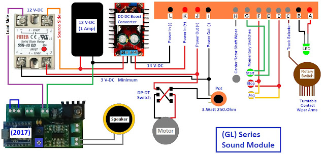
This is a wiring schematic of the complete project.
Turntable fine adjustment rotational speed at Slow Indexing Speed. Have the turntable constantly turning in slow jog mode by adding a jumper cable. Adjust the 3.Watt 250.Ohm variable resistor (potentiometer) having the turntable fully operational at the slowest operating speed.
Trouble Shooting: (No Sound)
(#1) Procedure
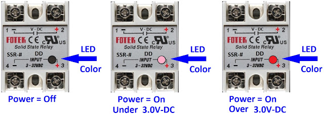
If the solid state relay (SSR) is not functioning correctly, the sound module will not receive the required 12.V-DC power supply. The operating LED will still operate under 3.V-DC but the internal
infrared LED's will not have enough voltage to operate correctly = (Pink Colour LED). The operating LED operating over 3.V-DC = (Red Colour LED). Place your heaviest locomotive onto the turntable. As previously done, add a jumper wire across terminals (F) and (D) onto the circuit board having the the turntable constantly rotating. Re-check that there is a 3.V-DC minimum power supply to the solid state relay.
Trouble Shooting: (No Sound)
(#2) Procedure
The above (#1) Procedure is functioning correctly. Place your heaviest locomotive onto the turntable. As previously done, add a jumper wire across terminals (F) and (D) onto the circuit board having the the turntable constantly rotating. Check that there is a 12.V-DC power supply to the sound module.
Direct e-mail contact only regarding my Blogs: gtrs.trains@gmail.com
© 2017 ITT Products (www.ittproducts.com/). ITTP Images and Sounds
Posted by Grand Trunk Railway Systems at Oct. 12 2017
Revised by Grand Trunk Railway Systems Jan. 09 / 2018


